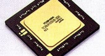
Toshiba announced the availability of a reference board for its newest 64-bit single-chip MIPS-based reduced instruction set computer (RISC) microprocessor, the 400-megahertz TX4939XBG-400. Designated RBTX4939, the new reference board complies with ATX specifications and includes most of the interfaces supported by the TX4939XBG-400.
Using the reference board, system designers can evaluate the basic performance and features of the microprocessor prior to building a prototype system. In addition, software designers can evaluate software drivers and develop application programs before a hardware prototype is made.
The RBTX4939 consists of two modules, a CPU module and a base board. The CPU module includes the TX4939XBG-400 microprocessor, DDR SDRAM and the EJTAG interface. The base board includes the PCI slots, ATA sockets, Ethernet PHY (RMII) and audio/video interface socket.
Since the CPU module contains enough circuitry to boot the TX4939XBG-400, customers can reuse the CPU module in their own designs if desired. Toshiba isolated the very high-frequency circuitry in the CPU module to free customers from concern about the DDR SDRAM design and layout when designing their own board to their desired specification.
The CPU module is equipped with the following:
- TX4939XBG-400 microprocessor - 256Mbyte DDR SDRAM (default), 4 x 512Mbit DDR SDRAM - Power supply circuit to drive the DDR SDRAM - EJTAG interface to enable the reading and writing of data - DIP switch for boot configuration - Reset, clock, real-time clock (RTC) circuit for the microprocessor
The base board includes two 10/100M Ethernet MACs (TX4939XBG-400's internal two Ethernet MACs and external PHY), NAND flash ROM (x8bit), two channels of ATA (IDE) interface, audio (AC-link/I2S) interface, five channels of PCI slot and a USB 2.0 host chip.
In addition, the base board includes NOR Flash ROM, four channels of RS-232C, a 100Base-TX Ethernet controller for debugging purposes, a ROM emulator connector, two ISA slots, an outside bus expansion connector, an input/output controller and a power supply circuit to supply a stable power supply to other locations throughout the board.

 14 DAY TRIAL //