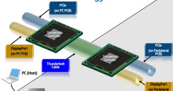
Back when Intel’s Thunderbolt was announced we had enough insider knowledge to know it was Intel’s attempt to practically expand a system’s add-on capabilities using PCI-Express.
The Thunderbolt technology was not a connectivity endeavor. It was a system extension.
With USB or FireWire you get a logic connection through a HUB or controller that’s visible to the operating system, and that has a special BUS through which the data is being transmitted.
The data transfer can be just as fast as the BUS would allow it to be and the controller itself would perform just as good as the PCIe lane it’s connected on.
This is generally a problem with the fast USB 3.0 controllers of our days. A fast controller might be able to handle four ports, but if you have devices that could saturate the 5000 Mb/s USB 3.0 connection on the controller, the PCIe connection of the controller itself might become the limiting factor.
Let us assume we have a device able to transfer data fast enough to saturate a 5000 Mb/s USB 3.0 connection. 5000 Mb/s translates into exactly 625 MB/s. Let’s say this is an external dual 2.5” drive enclosure with two cheap SSDs from ADATA or OCZ.
Two such SSDs in RAID 0 will generally provide sequential read speeds of around 650 MB/s, thus being a good fit for the maximum transfer of a USB 3.0 port of 625 MB/s.
A version 1.x PCIe lane can transfer 250 MB/s, so clearly a two-port USB 3.0 add-on PCIe 1x card mounted into a PCIe version 1.x slot won’t be able to handle even a third of the 625 MB/s potential transfer speed of just one of the two USB 3.0 ports.
Mounting the card into a PCIe 1x slot on a PCIe 2.0 capable motherboard will yield a maximum bandwidth of 500 MB/s for the add-on USB 3.0 controller. This still isn’t enough to satisfy the transfer ability of our external SSD RAID 0 enclosure.
When using a new motherboard with PCIe 3.0 support, the PCIe 1x add-on card will be serviced by a 1000 MB/s PCIe 1x 3.0 lane and will finally have enough bandwidth to fully enjoy the fast SSD RAID 0 enclosure.
Using a 1x slot on a PCIe 3.0 motherboard, one of the two USB 3.0 ports on the add-on card will be able to work at its highest theoretical speed and there is also at least 375 MB/s worth of bandwidth left to service the second USB 3.0 port on the add-on card.
On the other hand, if you’d try to connect two USB 3.0 devices capable of more than 600 MB/s transfer rates, the add-on card would require at least two PCIe 3.0 lanes with a total bandwidth of 2000 MB/s to satisfy the 1200 MB/s compound requirements of the two fast USB 3.0 external devices.
As there are no PCIe 2x slots, such an add-on card will have to have at least a PCIe 4x slot.
If we’re lucky to have a PCIe 4x slot on our PCIe 3.0 motherboard and a high performance USB 3.0 add-on card with a PCIe 4x connector, we could have at least six full-speed USB 3.0 ports available on the add-on card.
There are not many motherboards with a PCIe 4x slot. Even high-end motherboards usually have more PCIe 16x slots and some or none PCIe 1x slots.
The user will be able to install an add-on card with a PCIe 4x connector into a PCIe 16x slot, but that would be one PCIe 16x slot not available for a video card.
If more such slots are available, the user only gives up a multi video card setup like SLI or CrossFire. If just one PCIe 16x slot is available and no on board video with all the other PCIe slots being 1x, the situation becomes impossible.
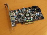
The third image presents such a PCIe 4x USB 3.0 add-on card, but the fact that for a long (say, 5 meters) connection with two devices you need two USB 3.0 that each are 5 meters long is a clear disadvantage.
What if you could take a PCIe “slot” 5 meters out of your system and then mount this USB 3.0 add-on card on it?
Moreover, what if you’d like to have a small box, full with PCIe “slots”, meters away from your motherboard, and you’d be able to connect to it using just one single cable while having many different devices connected througt it, directly to the PCIe BUS?
One example of such a "small" box, with PCIe “slots” in it, is Apple’s Thunderbolt display.
Thunderbolt solves this by simply taking a number of “virtual” PCIe slots and moving them outside the system. But more on how Thunderbolt works and what it brings new to the industry, in the next part of our Intel Thunderbolt presentation articles.

 14 DAY TRIAL //

